Measurements are in mm or ° unless stated
Brief
Aim: To fix my 3d printer’s wobbliness issues by tying it down like a cable-stayed bridge.
Idea: Top frame part, bottom frame part. Use flexible tie wire to loop from top to bottom then tighten with a screw of sorts.
I have a 3d printer that hasn’t been in action for over ⅔rds of a year now. It works, but the design has a major flaw; The top frame sits only ~15mm into the base and there aren’t sufficient screws to hold it. Furthermore, it’s held from the bottom. As the printer head gets higher, the head levers more and more. By applying pressure from above, I can secure the printer from both sides.
Example
Look at this wobbly goober
.png)
Design
.png) So far, this project is incomplete. I’ve designed and fabricated the top half- being the more important functional half- but the bottom half hasn’t got any measurements laid out. Nonetheless it’s the easier half and doesn’t require much more than measuring clearances.
Note: Later me has found an alternative to a bottom frame. Will update when this is installed.
So far, this project is incomplete. I’ve designed and fabricated the top half- being the more important functional half- but the bottom half hasn’t got any measurements laid out. Nonetheless it’s the easier half and doesn’t require much more than measuring clearances.
Note: Later me has found an alternative to a bottom frame. Will update when this is installed.
I measured the top section of my 3d printer from home and determined that 30×N flats would work as a main bar. The arms have 11mm holes to clear for the tightening mechanism.
The thin sides are to secure the cable-stay body to the printer’s top frame. The stock spool holder is secured with 2x M4 bolts that screw into heat set inserts. In this design, I do have the option to secure the cable-stay body like that, but all the pulling pressure would be centerd on those 2 small areas. Rather than that, some 1.8mm sheet metal prevents it from wobbling around
I experimented with some 10mm allthread to make a place for a tie-wire loop. With a nut, it sits on the top of the metal arm and slides through the hole. Once the tie wire is tight, I can use a spanner and flat head screw driver to tighten. I spitballed in the workshop making this, and conveniently I somehow measured a piece to be exactly 45mm long with a filed-flat edge 10mm long. After making the first one, I repeated the process by using the first as a yardstick.
SVG doodle very roughly explaining what my deisgn is.
.svg)
Fabrication Process
Tightening Rods
.png)
Recently to this project I had organised the locker that stocked the allthread rods, so I knew of an offcut that would suit this idea. Before cutting, I threaded on a nut which re-threaded the bit where I cut off. I secured these rods in the V-notch found on machine vices (portable, small jaw vices ideal for usage on a drill press) but learnt from my teacher of these blocks with v-notches in them designed for securing rods in bench vices.
I deburred one edge and chamfered the other using the pedestal grinder before unwinding the nut to recut the thread. I used a rasp to cut away a face of the thread (~2mm deep) so I could centre-punch and drill the tie wire holes. Unlike cutting sections of allthread, this stage was more ideal with machine clamps.
I then flip the thread so that the flat face is upside down and file away the other side with the goal of making the piece symmetric. To clean up I used a double-cut file on both sides.
The final step was to hacksaw in a flat head profile. I found that center-punching both the absolute center and direction I wished to cut (see below) made it easier to begin a cut. I held the hacksaw by its main handle and by pinching the safe side of the blade when doing this. Looking back, I could’ve just tightened the blade to make it rigid. Did you know they could be tightened? What mundane knowledge heh.
.png)
Due to the usage of vices, the allthread gets damaged in the process. Running a nut through the thread like at the start slowly cleans up the piece. (or, perhaps it just weakens the nut)
Note: With guilt I admit, I broke the last 2.75mm drillbit doing this project… forgive me!
Handtools Used
.png)
Result
.png)
.png)
Guards
The 1.8mm guards are 240×18mm and were cut from plasma laser off-cut sheets using an angle grinder. To try to achieve a rectangle rather than a weird wave, I used a scrap piece of metal to align my cuts with the saw. Looking back on this, there’s a lot of safety measures I could’ve added.
Originally I used some scrap 100×10 flat as that would provide more surface area to grip the clamp and it already had a clean edge, but I found it was far too heavy. Angle section offcut was far more effective. The angle grinder here is represented as an orange line.
.png)
I was careful not to lay the angle grinder on the support scrap, as that would bend and break the cutting disc. It was difficult to cut a straight line with this support and I ended up cutting a total of 5 guards, only 2 of which were usable. To do this better in future I want to find an unequal/shorter guide and spray some WD40 on the guide.
Danger
Do NOT use WD40 with a cutting disk. Yes I could just fix my typo that I wrote weeks ago, but only a couple days ago I learnt it was actually really flammable. There’s dedicated ‘cutting fluid’ stuff you can find at Bunnings. (or whatever hardware store that’s localised to you)
According to Neptonics silicone spray is better than WD40 for lubrication as it isn’t as greasy and it lasts longer, so try that.
Later on, after welding the guards on, I found a better method by using some scrap hollow section to act as a general height barrier. This way I could clamp my work to the table. I didn’t measure any specific length, just referred to the shorter of the two guards.
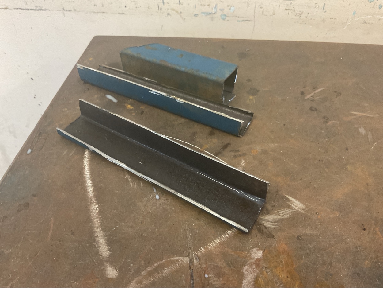
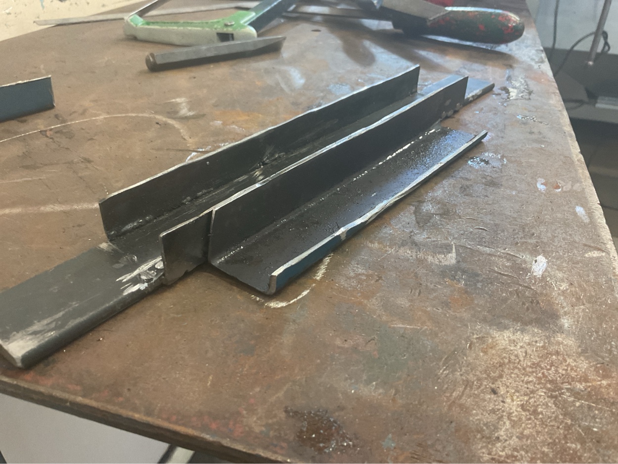
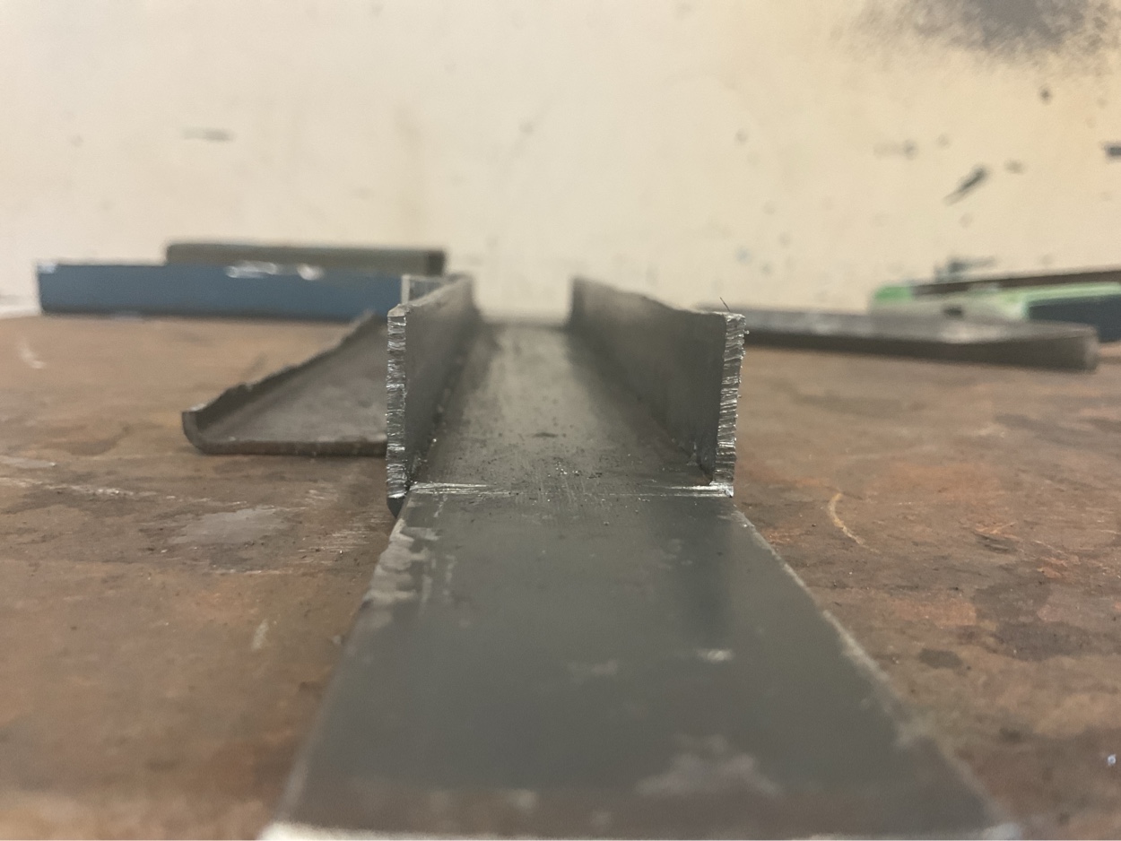
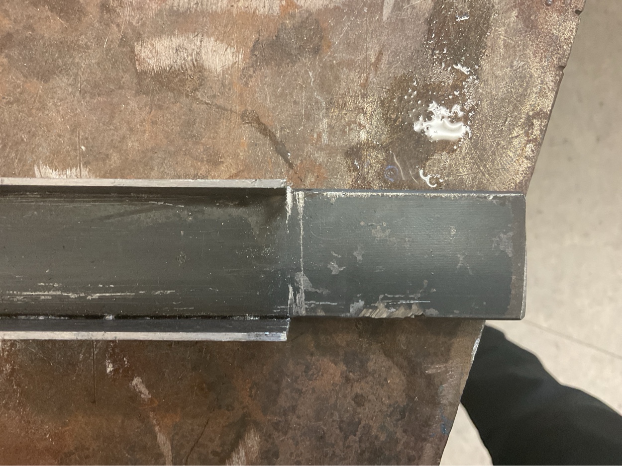
But yeah, far out, I’m super happy with how these turned out.
Arms
.png)
To centre the clearance holes, I used a spring compass to measure approximately halfway between the bar. Unlike sheet metal, flats are thicker therefore harder to accurately mark using a compass. With sheet metal, the height doesn’t make a substantial difference and the only thing you have to watch for is whether you’re holding the compass as far inwards as it can go.
.png)
With a metal flat (especially one that has a slight rounding to its edges) spring compasses are harder to use as you have to drive your hand further into the workbench (effectively marking the workbench more than the steel).
.png)
After finding the midpoint of thickness, marking the distance at the end was easy. 35 × ½ = 17.5, spring compass one point on edge and draw arc. Furthest point out is the place where I wanted to drill. I center-punched and used the belt-driven drillpress.
Result
.png)
Welding
Earlier I’ve written “30×N flats” as the material used for the arms and main bar. I ended up using 31×5 flats. I noticed that the edges aren’t square, so I planned to cut away some material using an angle grinder. An even more convenient solution was to just place the 1.8mm guards on the inside rather than outside.
Guards
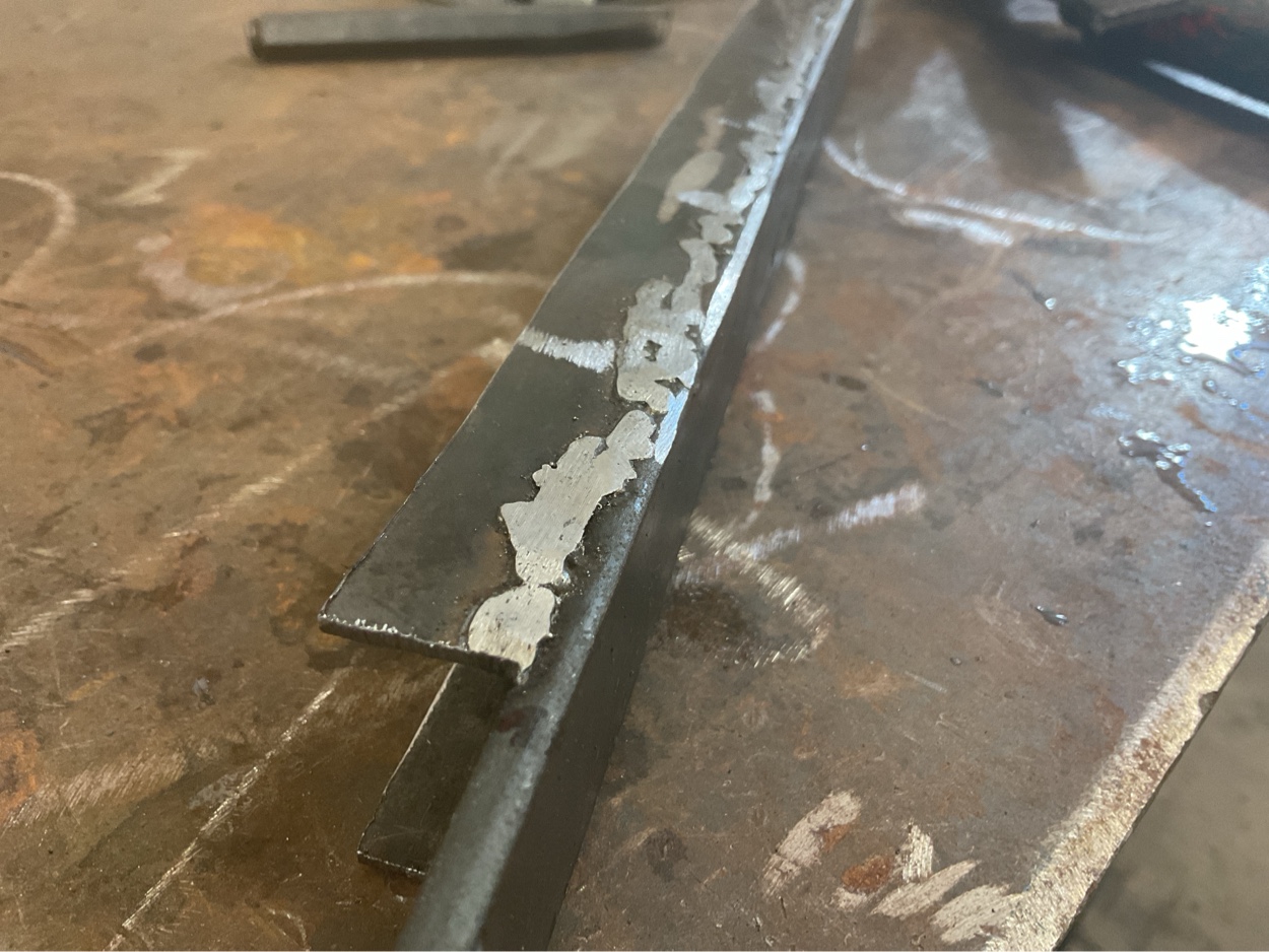
The first weld was a guard. I used spare 30mm square hollow section as a way to ensure that the thickness would be 18mm. The weld was relatively messy and I still need to practice, but I’ve been able to fix it with an angle grinder.
.png)
This first weld was relatively messy and there was a point I burnt through the metal. I had the welding unit set to ~8m/min of wire speed and 15.5V. Lowering the wire speed to ~4.5m/min and reducing the voltage to a flat 15V turned the welding gun into something more like a gap filler.
The following is a much later photo when I had ground down the extra weld completely.
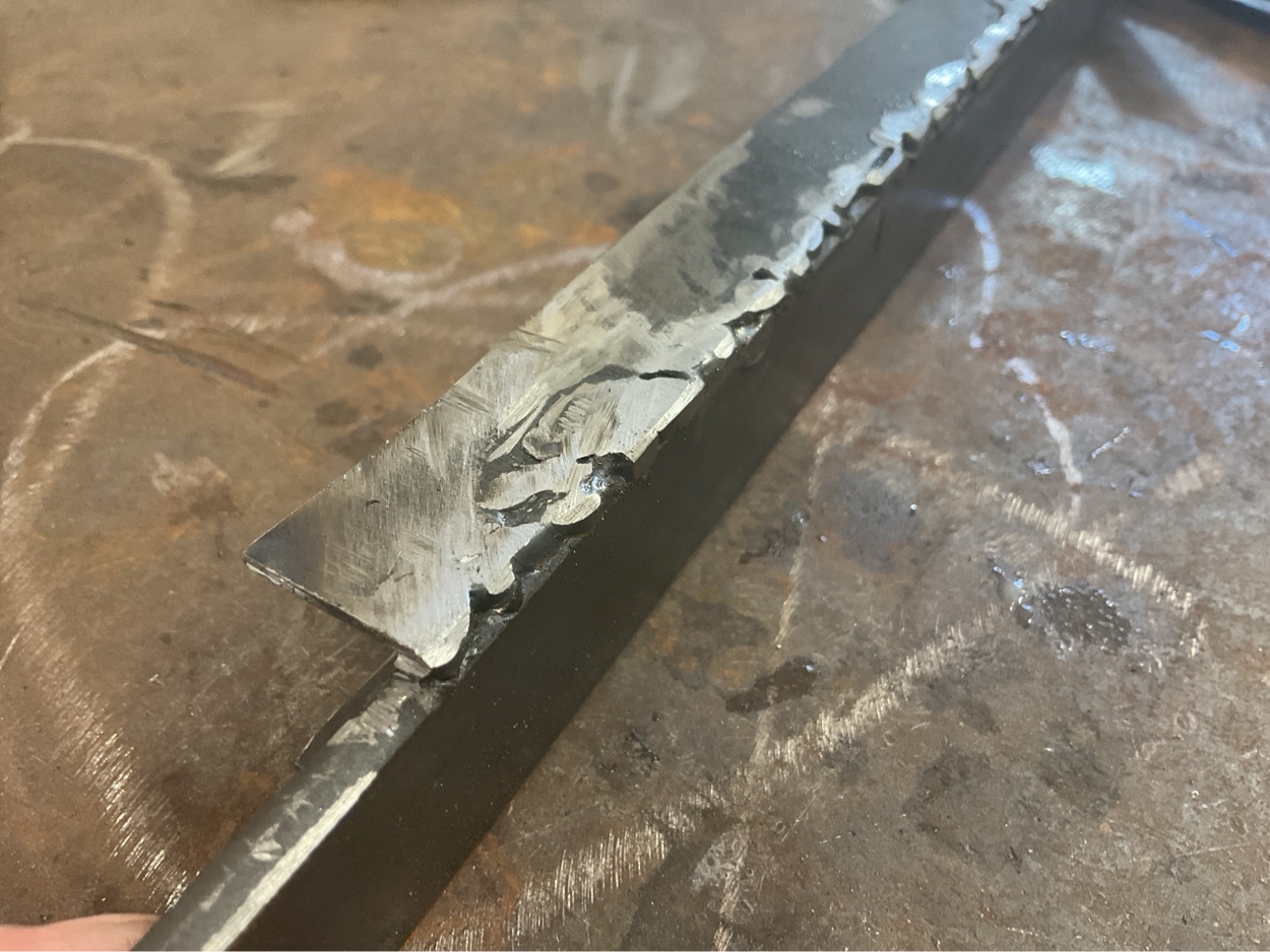
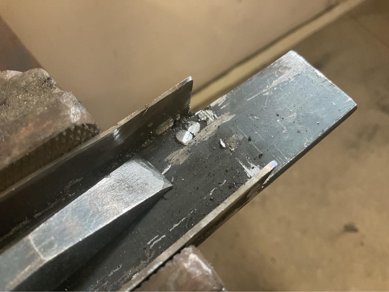
I had to clean up the inside afterwards, which I spent too long trying to do with a file only to realise “Wait, I have chiselling good looks chisels”
My Proudest Welds (Arms)
Genuinely so happy with these corner welds. The following photos aren’t cleaned up. This is straight from workbench to storage.
.png)
.png)
.png)
.png)
Where next?
I’ll write a separate blog post for the installation. Thankyou for reading through this. I got some great hands-on experience with the angle grinder with this project, and I’m feeling somewhat ecstatic with the thought of getting my 3d printer running again. What you’ve just read is my heavily edited / expanded school work writeup. I’m glad I did the documentation of my learning as a blog post; finally, something I can shelve in my library of writing.